Area of application
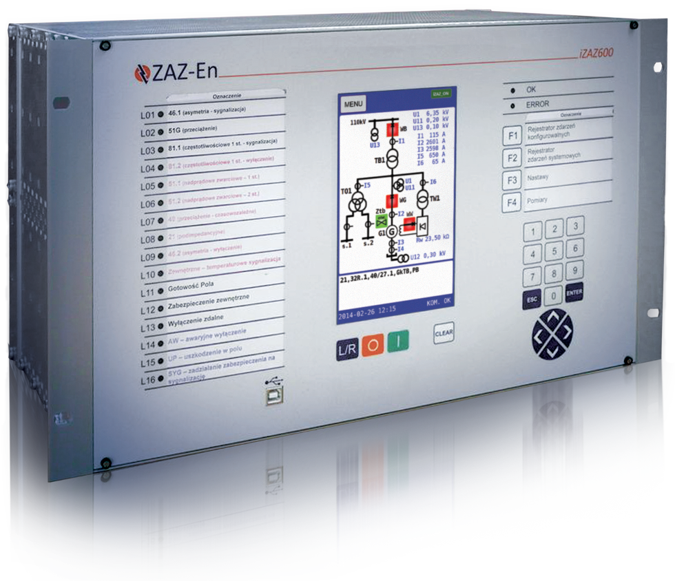
iZAZ600 is a series of powerful, communication-enabled digital multifunctional relays with up to 48 measurement inputs. These devices are characterised by high accuracy and reliable operation, they can be used in automatic control systems as comprehensive protection devices for generators operating directly on busbars, and generator-transformer blocks. Apart from the protection and automatic control functions, the devices enable measurements, recording, emergency control and signalling. Methods of communication with the system include: four serial ports in various physical configurations (RS-232, RS-485, fibre), wire or fibre ETHERNET connection and a USB port on the control panel. Thanks to the modular design, the hardware configuration can be optimally customised to the requirements of the protected facility. A 7-inch colour touch display ensures legible presentation of the bay synoptic system with essential measurements and additional information. The operation logic is easily programmable via a graphic editor, which enables legible and transparent implementation of various applications, both typical and dedicated, including specific requirements for a given facility. Bay controller enables the control of circuit-breaker and switching devices, while maintaining the required functional interlocks.
The universal hardware and software enable easy and intuitive changing of the configuration and adaptation to various facilities. With the application base developed by the manufacturer, default solutions can be used. Moreover, it is possible to modify the configuration to match the specifics of the protected facility, and the user needs. The modification of the configuration can include adding protective functions or automatic controls and the change of logic-time dependencies (e.g. means of controlling diodes on the panel, signalling on the display, controlling signalling relays and means of emergency control).
Recorders
The device is equipped with three different recorders enabling the analysis of phenomena occurring in the protected facility.
Event recorder – basic status recorder creating a chronological event log with a resolution of 1 ms. Circular buffer with a capacity of 1000 events. It records protective device excitations, reactivations and operations as well as status changes of binary inputs, automatic controls, and other events generated from the internal logic. Names and comments can be edited for all events, which allows application adaptation and facilitates the analysis of interferences by the user.
Actuation recorder – enables quantitative analysis of the interferences. This recorder contains information about the interference time and threshold parameters of signals measured from the moment of excitation to reactivation of the function after its operation. The type and amount of recorded data depend on the nature of the function, e.g. for overcurrent protection it is the interference duration and maximum current value in this time frame. Actuation recorder enables quick assessment of the event by presenting information on criterion values associated with the interference. This also gives the user the opportunity to verify settings. For a typical record of three analogue values (e.g. maximum current or voltage), the internal circular buffer allows recording up to 200 records.
Disturbance recorder – a set of recorders of analogue and binary waveforms with criterion recorder function enabling full analysis of interfering phenomena. The device allows programming of up to four fully independent configurable recorders. The function of criterion recorder offers the opportunity of recording any of the criterion values available in the device (analogue and binary). The standard settings of pre-run, post-run and maximum recording time enable proper shaping of the log window for the phenomenon of interest. In order to optimize the recording of long term low-frequency phenomena, it is possible to lower the sampling rate with the option of controlling rarefaction of the recorder log using a chosen binary signal (e.g. circuit-breaker open, etc.). The capacity of the internal buffer depends on the number of active recorders, programmed analogue and binary channels, and the maximum duration of the individual recording. For a single recorder, 8 analogue channels, and 64 binary channels, it is possible to record a 1000-second file.
Functional characteristics
- An extensive set of protective functions and automatic controls
- Extensive list of available measurements, such as measurement of all currents and voltages, and calculated values (e.g. power and energy, frequency, temperature from the model)
- Programmable controller with a legible graphic interface enabling the implementation of various logic-time dependencies on the basis of all signals available in the device
- Counters enabling diagnostics of the working status of the bay (including: number of protection device operations, automatic control operations, trips, cumulated counter of circuit-breaker currents)
- Operation logic easily programmable using a graphic interface
- Recorder of configurable and system events
- Actuation recorder
- Disturbance recorder with the function of the criteria recorder
- Indicator of qualitative energy coefficients: THD, frequency, number of voltage losses, dips
- Up to 48 measurement inputs (hardware-configurable: currents, voltages, 4–20 mA or PT-100 sensor inputs)
- Up to 233 fully programmable output relays in various configurations, including 8 high-power reed relay contacts for direct control of circuit-breaker coils
- Up to 128 programmable binary inputs for visualizing the switching device status and interoperating with external protection devices
- 16 programmable, two-colour signalling diodes on the control panel
- Extended autotest system with warning signalling
- Real time clock with sync capability
- Communication with a PC or parent system via up to four RS-232/RS-485 or LAN (wire or fibre) interfaces and standard USB port at the front panel
- Control panel with a legible 7-inch colour graphical touch display, navigation and numerical keyboard with a standalone mounting capability
- Standard package of application software - iZAZ Tools (including iREC software for disturbance recordings analysis)
- Digital technology ensuring high stability, accuracy and reliability of operation
- Protection against unauthorised access (setting or configuration modification)